- 您现在的位置:买卖IC网 > Sheet目录1991 > CS53L21-CNZR (Cirrus Logic Inc)IC ADC STEREO 24BIT 98DB 32-QFN
14
DS700PP1
CS53L21
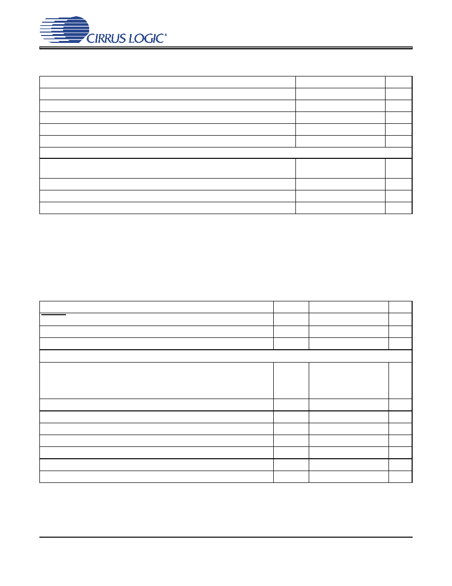
ADC DIGITAL FILTER CHARACTERISTICS
6. Response is clock-dependent and will scale with Fs. Note that the response plots (Figures 23 to 26) have
been normalized to Fs and can be de-normalized by multiplying the X-axis scale by Fs. HPF parameters
are for Fs = 48 kHz.
SWITCHING SPECIFICATIONS - SERIAL PORT
(Inputs: Logic 0 = DGND, Logic 1 = VL, SDOUT CLOAD = 15 pF.)
Parameter (Note 6)
Min
Typ
Max
Unit
Passband (Frequency Response)
to -0.1 dB corner
0
-
0.4948
Fs
Passband Ripple
-0.09
-
0.17
dB
Stopband
0.6
-
Fs
Stopband Attenuation
33
-
dB
Total Group Delay
-
7.6/Fs
-
s
High-Pass Filter Characteristics (48 kHz Fs)
Frequency Response
-3.0 dB
-0.13 dB
-
3.7
24.2
-
Hz
Phase Deviation
@ 20 Hz
-10-
Deg
Passband Ripple
-
0.17
dB
Filter Settling Time
-105/Fs
0
s
Parameters
Symbol
Min
Max
Units
RESET pin Low Pulse Width
1-
ms
MCLK Frequency
1.024
38.4
MHz
MCLK Duty Cycle
45
55
%
Slave Mode
Input Sample Rate (LRCK)
Quarter-Speed Mode
Half-Speed Mode
Single-Speed Mode
Double-Speed Mode
Fs
4
8
4
50
12.5
25
50
100
kHz
LRCK Duty Cycle
45
55
%
SCLK Frequency
1/tP
-64Fs
Hz
SCLK Duty Cycle
45
55
%
LRCK Setup Time Before SCLK Rising Edge
ts(LK-SK)
40
-
ns
LRCK Edge to SDOUT MSB Output Delay
td(MSB)
-52
ns
SDOUT Setup Time Before SCLK Rising Edge
ts(SDO-SK)
20
-
ns
SDOUT Hold Time After SCLK Rising Edge
th(SK-SDO)
30
-
ns
发布紧急采购,3分钟左右您将得到回复。
相关PDF资料
CS5509-ASZR
IC ADC 16BIT SGL SUPP 16-SOIC
CS5512-BSZ
IC ADC 20BIT EXTERNAL OSC 8-SOIC
CS5526-BSZR
IC ADC 20BIT W/4BIT LATCH 20SSOP
CS5528-ASZR
IC ADC 24BIT 8CH 24-SSOP
CS5529-ASZR
IC ADC 16BIT W/6BIT LATCH 20SSOP
CS5530-ISZR
IC ADC 24BIT 1CH W/LNA 20-SSOP
CS5534-ASZR
IC ADC 24BIT 4CH W/LNA 24-SSOP
CS5534-BSZR
IC ADC 24BIT 4CH W/LNA 24SSOP
相关代理商/技术参数
CS53L21-DNZ
制造商:Cirrus Logic 功能描述:IC LW-POWER STEREO ANALOG-TO-DIGITAL ADC - Rail/Tube 制造商:Cirrus Logic 功能描述:IC ADC STEREO 24BIT 96KHZ 32QFN
CS53L21-DNZR
制造商:Cirrus Logic 功能描述:IC LW-POWER STEREO ANALOG-TO-DIGITAL ADC - Tape and Reel 制造商:Cirrus Logic 功能描述:IC ADC STEREO 24BIT 96KHZ 32QFN
CS53L30-CNZ
制造商:Cirrus Logic 功能描述:IC ADC 24BIT STER 16KHZ 32QFN 制造商:Cirrus Logic 功能描述:Audio A/D Converter ICs 4 Mic ADC 制造商:Cirrus Logic 功能描述:ADC, 24BIT, 16KSPS, I2C, QFN-32, Resolution (Bits):24bit, Sampling Rate:16kSPS,
CS53L30-CNZR
功能描述:IC ADC 24BIT STER 16KHZ 32QFN 制造商:cirrus logic inc. 系列:- 包装:带卷(TR) 零件状态:在售 类型:ADC,音频 分辨率(位):24 b 采样率(每秒):16k 数据接口:I2S 电压源:单电源 电压 - 电源:1.71 V ~ 1.89 V 工作温度:-10°C ~ 70°C 安装类型:表面贴装 封装/外壳:32-VFQFN 裸露焊盘 供应商器件封装:32-QFN(5x5) 基本零件编号:CS53L30 标准包装:6,000
CS53L30-CWZR
功能描述:音频模/数转换器 IC 4 Mic ADC
RoHS:否 制造商:Wolfson Microelectronics 转换速率: 分辨率: ADC 输入端数量: 工作电源电压: 最大工作温度: 最小工作温度: 安装风格: 封装 / 箱体: 封装:
CS53L32A
制造商:CIRRUS 制造商全称:Cirrus Logic 功能描述:Low Voltage, Stereo A/D Converter
CS53L32A-BZ
制造商:CIRRUS 制造商全称:Cirrus Logic 功能描述:Low Voltage, Stereo A/D Converter
CS53L32A-KZ
制造商:Rochester Electronics LLC 功能描述:LOW VOLTAGE A/D CONVERTER - Bulk 制造商:Cirrus Logic 功能描述: